Коммутация в Mikrotik — Bridge и Master-port
В RouterOS есть два способа коммутации портов.
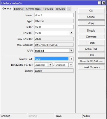
Коммутация портов MikroTik через Switch (Master Port)
В этом случае коммутация производится через чип свитча, в обход центрального процессора маршрутизатора. Обычно в SOHO маршрутизаторах Mikrotik используется одна свитч-группа на 5 портов, если портов больше — две свитч-группы. В устройствах Cloud Router Switch чипы коммутации на больше портов и имеют больше возможностей, подробней на них мы останавливаться в этой статье не будем.
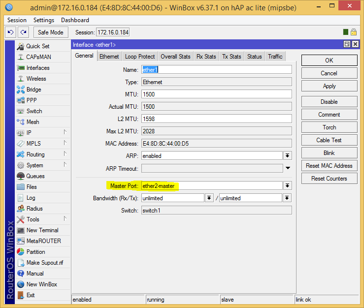
Настроить коммутацию можно в разделе General каждого порта, просто выбрав в пункте Master Port. Это главный порт, через который будет происходить коммутация. Коммутация позволяет достичь проводной скорости обмена данными между портами одной группы, как между портами в обычном Ethernet-коммутаторе. Основной (master) порт будет являться портом, через который RouterOS будет сообщаться со всеми остальными портами данной группы. Интерфейсы, для которых задан master-порт, становятся неактивны – не учитывается поступивший и отправленный трафик. Фактически, как будто мы объединили порты физическим, «тупым» коммутатором (свитчем). В роутерах Mikrotik применяются следующие чипы коммутации:
Возможности чипов коммутации:
| Возможности | Atheros 8316 | Atheros 8327 | Atheros 7240 | ICPlus 175D | Другие |
|---|---|---|---|---|---|
| Коммутация портов | да | да | да | да | да |
| Зеркалирование портов | да | да | да | да | нет |
| Таблица MAC-адресов | 2000 записей | 2000 записей | 2000 записей | нет | нет |
| Vlan-таблица | 4096 записей | 4096 записей | 16 записей | нет | нет |
| Таблица правил | 32 правила | 92 правила | нет | нет | нет |
* Порт ether1 на RB450G имеет особенность, которая позволяет ему быть исключённым/добавленным из/в коммутируемой(ую) группы(у) по умолчанию. По умолчанию порт ether1 будет включён в группу коммутации. Данная конфигурация может быть изменена с помощью команды
«/interface ethernet switch set switch1 switch-all-ports=no».
switch-all-ports=yes/no:
«yes» означает, что порт ether1 является портом коммутатора и поддерживает создание групп коммутации и все остальные расширенные возможности чипа Atheros8316, включая расширенную статистику (/interface ethernet print stats).
«no» означает, что порт ether1 не является частью коммутатора, что, фактически, делает его самостоятельным Ethernet-портом – это способ увеличения пропускной способности между ним и другими портами в режимах сетевого моста и маршрутизации, но в то же время исключает возможность коммутации на этом порту. Коммутация через Switch является самой быстрой и производительной в маршрутизаторе, в тоже время имеет наименьшее количество возможностей. При этом:
Итого, можно выделить несколько особенностей такого метода:
Коммутация в MikroTik через Bridge-interface
Порты объединяются не напрямую, а программно, используя ресурсы центрального процессора маршрутизатора. К портам могут быть применены фильтры брандмауэра. Такое объединение так-же влияет на прохождение пакетов по упрощенной схеме (Fastpath). Если взять в пример 2011-серию маршрутизаторов, то ether1-ether5 объеденены в switch1 (Atheros 8327) а ether6-ether10 в switch2 (Atheros 8227), вы можете использовать только Bridge для объединения их в одно целое. Особенность данного метода:
Коммутация позволяет достичь проводной скорости (wire speed) обмена данными между портами одной группы, как между портами в обычном Ethernet-коммутаторе.
Пока пакет не достиг cpu-порта, его обработка полностью осуществляется логикой коммутатора, не требуя какого-либо участия центрального процессора, и эта обработка происходит с проводной скоростью при любом размере кадра.
Пропала опция Master-port и поле Switch
Не пугайтесь, это нормально, если прошивка вашего роутера 6.41 и выше. Теперь вся информация, которая передается на втором уровне модели OSI, будет передаваться через Bridge. Использование swich-чипа (hw-offload) будет автоматически активировано автоматически в случае такой возможности. По умолчанию при добавлении любого интерфейса в Bridge у него будет активирована опция «Hardware Offload», которая будет передавать всю информацию 2-го уровня через switch-чип. Если эту опцию убрать, то обработка будет осуществляться силами операционной системы.
При обновлении на RouterOS 6.41 и выше с RouterOS версий 6.40.5 и ниже все настройки master-port будут автоматически перенесены в Bridge-интерфейс. Если произвести downgrade до версии, которая поддерживает master-port, то настройки не будут возвращены на место. Настоятельно рекомендуется сделать резервную копию до обновления.
До обновления до RouterOS 6.41:
/interface ethernet set [ find default-name=ether1 ] name=ether1-WAN1 set [ find default-name=ether5 ] name=ether5-LAN1-master set [ find default-name=ether2 ] master-port=ether5-LAN1-master name=ether2-LAN1 set [ find default-name=ether3 ] master-port=ether5-LAN1-master name=ether3-LAN1 set [ find default-name=ether4 ] master-port=ether5-LAN1-master name=ether4-LAN1 /ip address add address=10.10.10.1/24 interface=ether1-WAN1 network=10.10.10.0 add address=192.168.0.1/24 interface=ether5-LAN1-master network=192.168.0.0 /ip firewall nat add action=masquerade chain=srcnat out-interface=ether1-WAN1
После обновления на RouterOS 6.41 и старше:
/interface bridge add admin-mac=6C:3B:6B:4A:80:3D auto-mac=no comment=»created from master port» name=bridge1 protocol-mode=none /interface ethernet set [ find default-name=ether1 ] name=ether1-WAN1 set [ find default-name=ether2 ] name=ether2-LAN1 set [ find default-name=ether3 ] name=ether3-LAN1 set [ find default-name=ether4 ] name=ether4-LAN1 set [ find default-name=ether5 ] name=ether5-LAN1-master /interface bridge port add bridge=bridge1 interface=ether2-LAN1 add bridge=bridge1 interface=ether3-LAN1 add bridge=bridge1 interface=ether4-LAN1 add bridge=bridge1 interface=ether5-LAN1-master /ip neighbor discovery-settings set discover-interface-list=!dynamic /ip address add address=10.10.10.1/24 interface=ether1-WAN1 network=10.10.10.0 add address=192.168.0.1/24 interface=bridge1 network=192.168.0.0 /ip firewall nat add action=masquerade chain=srcnat out-interface=ether1-WAN1
Mikrotik – bridge или Master-slave?
Раньше все необходимые порты для объединения в локальную сеть закидывал в бридж. Так вот – это не правильно.
Грубо говоря, лучше делать так – возьмём стандартную ситуацию, по типу домашнего роутера, на примере 951-2n – один интернет, 4 лан-клиента + WiFi. Первый порт понятно WAN, второй мы соединяем бриджем с WiFi, а остальные подключаем слейвами ко второму.
То есть должно получиться, что-то подобное –
“Коммутация позволяет достичь проводной скорости (wire speed) обмена данными между портами одной группы, как между портами в обычном Ethernet-коммутаторе”
“Пока пакет не достиг cpu-порта, его обработка полностью осуществляется логикой коммутатора, не требуя какого-либо участия центрального процессора, и эта обработка происходит с проводной скоростью при любом размере кадра.”
В общем, при включении в бридж, не задействуются возможности чипа коммутации. И начинаются проблемы по скорости (и ещё некоторые другие, из-за которых я и полез туда). Особо это заметно на 2011 серии (и думаю на всех более старших), при работе с гигабитными портами.
Про 2011 серию. В них установлено два чипа коммутации Atheros 8327 (ether1-ether5+sfp1) и Atheros8227 (ether6-ether10). Так что надо создавать 2 группы свитч-портов при помощи указания Master-port на интерфейсах. А уже мастер-порты объединить в бридж. Снизит нагрузку на CPU при проходе трафика между портами одной группы.
#mikrotik #routeos #bridge #disnetern
Mikrotik с нуля. 04 Коммутация
Ранее уже обсуждалось, что RouterBOARD может в себя включать встроенный коммутатор.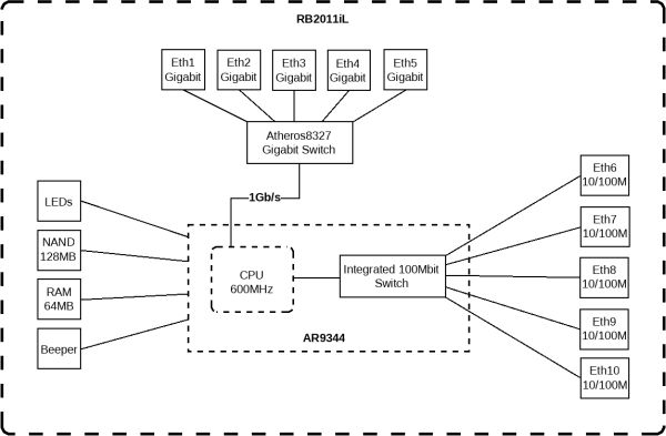
В данной схеме устройство в себе объединяет два чипа коммутации: гигабитный и 100мбитный.
Любой порт данного устройства можно либо объединить в логически единый коммутатор, либо порт может работать отдельно, на 3-м уровне.
Нужно понимать что сам по себе чип коммутации способен коммутировать без участия процессора, при этом существуют разные чипы коммутации, которые могут быть включены в состав RouterBOARD.
https://wiki.mikrotik.com/wiki/Manual:Switch_Chip_Features
Выше приведена диаграмма RB2011, в составе которого входят два чипа: Atheros8327 (ether1-ether5+sfp1); Atheros8227 (ether6-ether10)
Возможности данных чипов приведена ниже: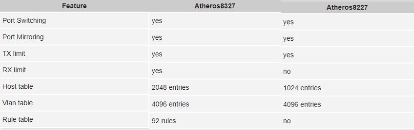
hAP ac lite (RB952Ui-5ac2nD)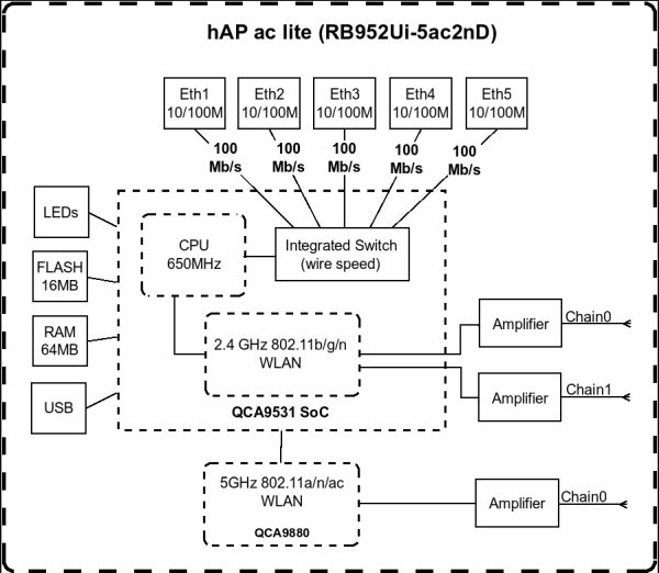
hAP ac lite имеет на борту чип Atheros8227 (ether1-ether5)
На уровне switch мы можем управлять элементами:
— switch
— port
— port-isolation
— host
— vlan
— rule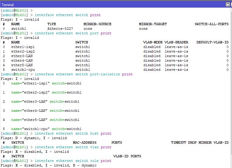
При этом при попытке создать rule, мы получим ошибку, поскольку данный switch не поддерживает rule.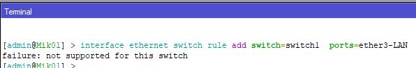
Объединение портов
Здесь стоит упомянуть, что до версии 6.41 в коммутации было понятие master-port.
После версии 6.41 все объединения портов выполняются через bridge.
Поэтому не рекомендуется даунгрейдить на версию ниже 6.41
Далее весь материал будет применяться к версии 6.41 и старше.
Итак, принадлежность портов к тому или иному свитчу или чипу можно определить командами:
interface ethernet print
interface ethernet switch port print
Как видно, в данной модели RouterBOARD все порты «живут» на одном чипе switch1.
Например, hAP ac lite имеет на борту чип Atheros8227 (ether1-ether5). И при включении функции Bridge VLAN Filtering, Hardware Offload будет невозможна, т.к. данный чип не поддерживает эту функцию. Hardware Offload будет автоматически отключена и в обработке коммутации Bridge будет участвовать CPU.
Fast Path
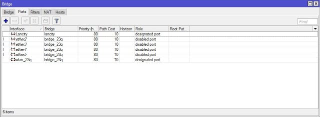
Настройка Bridge
Как видно, мы добавили все три порта в Bridge. Теперь все IP адреса должны «жить» на интерфейсе Bridge.
DHCP также должен быть привязан к интерфейсу Bridge
interface bridge port print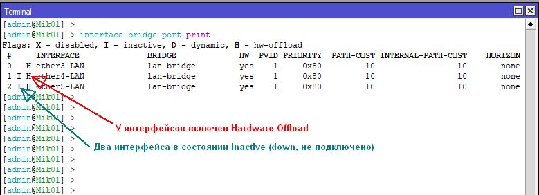
Если добавить в созданный Bridge интерфейсы wifi:
interface bridge port print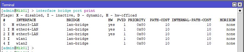
Как видно, на интерфейсах wlan отсутствует Hardware Offload. Это из-за того, что интерфейсы wlan «не живут» на чипе switch
Mikrotik: VLAN с использованием чипа коммутации
Вступление
Итак, вокруг множество статей, где с VLAN работаю на CPU (объявляют VLAN на интерфейсе и помещают его в Bridge). Такая связка имеет право на жизнь, но в её работе мы расходуем ресурс CPU, который может быть очень ценным. Два разных устройства представляют различные механизмы настройки для чипа коммутации, так как они сильно разные в техническом плане.
Реализовывать будем некоторые примеры из официальной Wiki:
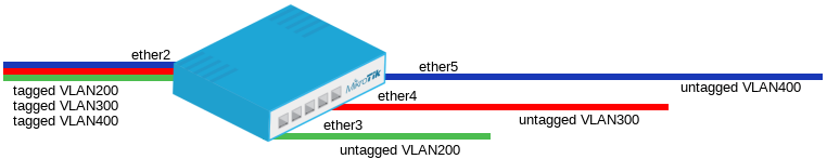
Port Based VLAN

Поясним картинку: На порт ether2 приходят тегированные пакеты (порт транковый), а с портов ether6-ether8 уходят растегированные пакеты (порты доступа — клиентские порты).
Я буду брать конфигурацию с реально работающего устройства, поэтому полного соответствия с картинкой не будет.
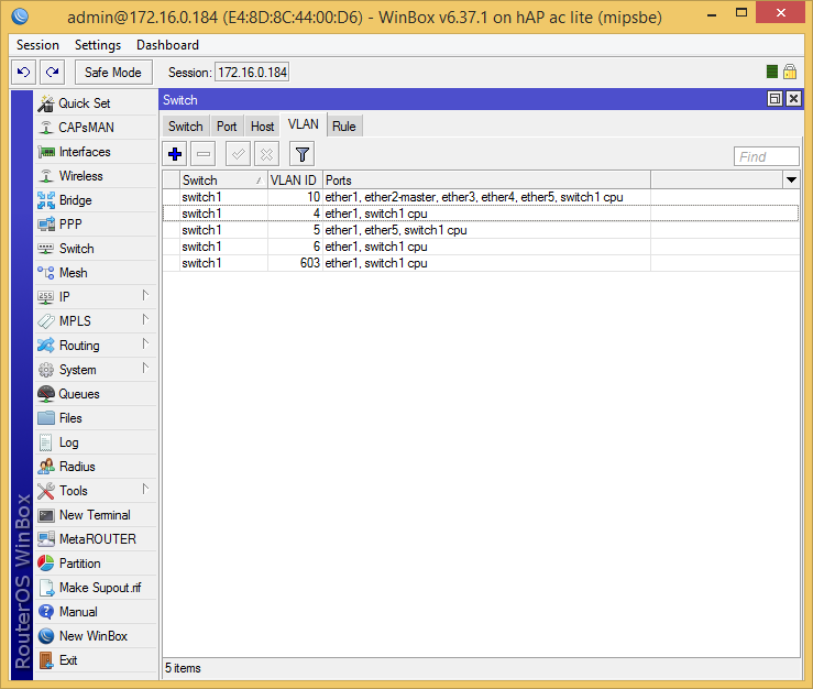
RB951Ui-2HnD
Конфигурация: На ether1 приходят тегированные пакеты (VID: 4,5,6,10, 603), с портов ether2-ether4 уходят раздетые VID:10, с ether5 уходит раздетый VID:5, VID:603 сейчас не используется, а особый порт switch1-cpu принимает любые пакеты.
Вначале, создадим группу коммутации, для этого, во всех интерфейсах выставим мастер порт (по умолчанию ether2-master), тем самым мы отдадим эти порты в управление коммутатору.
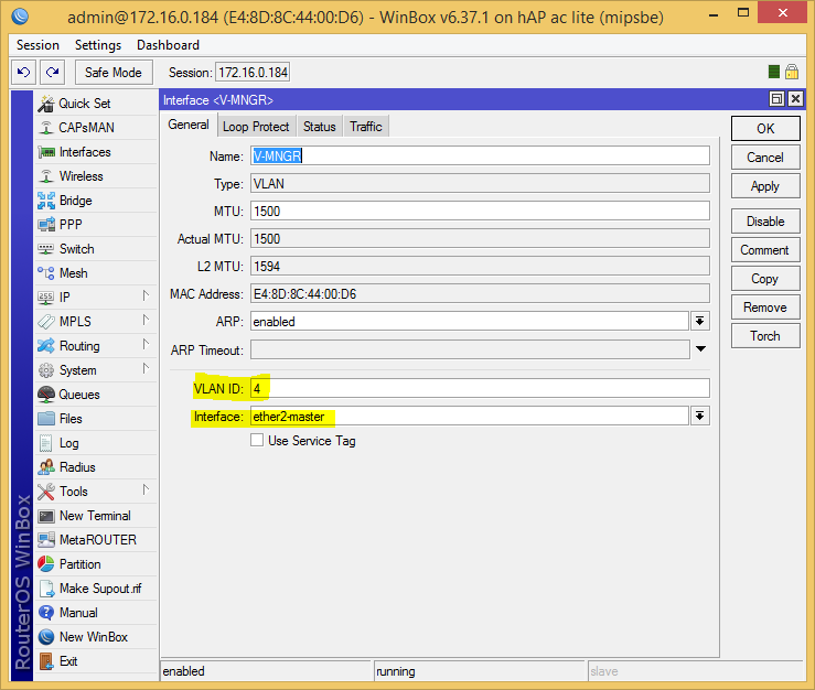
Аналогично для всех остальных. Не затягивая, на мастер порт (так мы получим доступ к этому VLAN из CPU, по сути мы связываем его с switch1-cpu) подвесим нужные нам VLAN:
Далее зададим политику обработки пакетов на портах (номер VLAN по умолчанию), что отбросить, что раздеть, а где и шарфик повязать:
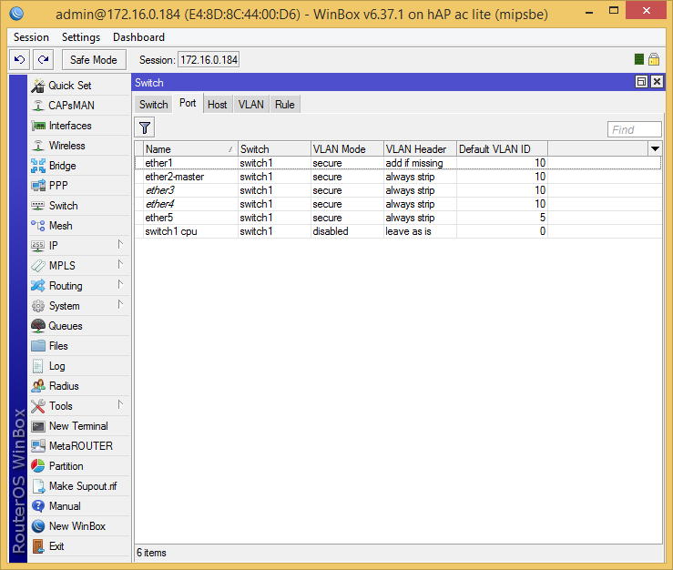
О параметрах можно почитать в Wiki в разделе Vlan-таблица.
Далее, мы создадим таблицу VLAN, по которой чип будет работать с тегами:
Вот и все, теперь VLAN обслуживаются на чипе коммутации, к сожалению, у RB951Ui-2HnD его возможности не очень большие, к примеру он не сможет сделать гибридный порт, тут придется строить лес из костылей на bridge.
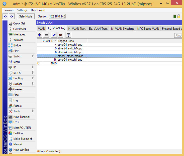
CRS125-24G-1S-2HnD
Тут чип коммутации совсем другой, и умеет больше, приступим:
Конфигурация: На ether24 приходят тегированные пакеты (VID: 4,5,6,7,16), с портов ether1-ether23 уходят раздетые VID:16 и одетые VLAN:7 (будет для второго примера), а особый порт switch1-cpu принимает любые пакеты.
Вначале, создадим группу коммутации, для этого, во всех интерфейсах выставим мастер порт (по умолчанию ether2-master), тем самым мы отдадим эти порты в управление коммутатору.
Аналогично для всех остальных. На мастер порт подвесим нужные нам VLAN:
Далее, мы создадим таблицу VLAN, по которой чип будет работать с тегами:

Далее зададим политику обработки пакетов на портах, тут уже все побогаче, политика задается раздельно.
Зададим порты, на которых соответсвующий VLAN будет одетым при выходе:
Теперь, на каких портах, выходящий VLAN надо раздеть:

Дословно это описывается так: если VID: 16, порт с 1 по 23, установить новый VID:0 (раздеть).
Теперь, на каких портах, входящий пакет надо одеть в VLAN:
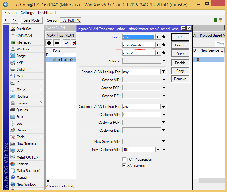
Дословно это описывается так: если VID: 0 (пакет раздетый), порт с 1 по 23, установить новый VID:16 (одеть).
Example 2 (Trunk and Hybrid ports)
Тут мы рассмотрим только CRS125-24G-1S-2HnD, к сожалению, RB951Ui-2HnD такое на чипе коммутации уже не умеет.
Итак, возьмем полностью конфу из предыдущего примера, и добавим такое правило:
Manual:Switch Chip Features

Applies to RouterOS: v6.0 +
Contents
Introduction
There are several types of switch chips on Routerboards and they have a different set of features. Most of them (from now on «Other») have only basic «Port Switching» feature, but there are few with more features:
Capabilities of switch chips:
| Feature | QCA8337 | Atheros8327 | Atheros8316 | Atheros8227 | Atheros7240 |
|---|---|---|---|---|---|
| Port Switching | yes | yes | yes | yes | yes |
| Port Mirroring | yes | yes | yes | yes | yes |
| TX limit | yes | yes | yes | yes | yes |
| RX limit | yes | yes | no | no | no |
| Host table | 2048 entries | 2048 entries | 2048 entries | 1024 entries | 2048 entries |
| Vlan table | 4096 entries | 4096 entries | 4096 entries | 4096 entries | 16 entries |
| Rule table | 92 rules | 92 rules | 32 rules | no | no |
| Feature | ICPlus175D | MT7621 | RTL8367 | 98PX1012 | Other |
|---|---|---|---|---|---|
| Port Switching | yes | yes | yes | no | yes |
| Port Mirroring | yes | yes | yes | no | no |
| TX limit | no | no | no | no | no |
| RX limit | no | no | no | no | no |
| Host table | no | 2048 entries | 2048 entries | no | no |
| Vlan table | no | no | no | no | no |
| Rule table | no | no | no | no | no |
Note: Cloud Router Switch (CRS) series devices have highly advanced switch chips built-in, they support wide variety of features. For more details about switch chip capabilities on CRS1xx/CRS2xx series devices check the CRS1xx/CRS2xx series switches manual, for CRS3xx series devices check the CRS3xx series switches manual.
| RouterBoard | Switch-chip description |
|---|---|
| RB4011iGS+ | RTL8367 (ether1-ether5); RTL8367 (ether6-ether10); |
| RB1100AHx4 | RTL8367 (ether1-ether5); RTL8367 (ether6-ether10); RTL8367 (ether11-ether13) |
| RB750Gr3 (hEX), RB760iGS (hEX S) | MT7621 (ether1-ether5) |
| RBM33G | MT7621 (ether1-ether3) |
| RB3011 series | QCA8337 (ether1-ether5); QCA8337 (ether6-ether10) |
| RB OmniTik ac series | QCA8337 (ether1-ether5) |
| RBwsAP-5Hac2nD (wsAP ac lite) | Atheros8227 (ether1-ether3) |
| RB941-2nD (hAP lite) | Atheros8227 (ether1-ether4) |
| RB951Ui-2nD (hAP); RB952Ui-5ac2nD (hAP ac lite); RB750r2 (hEX lite); RB750UPr2 (hEX PoE lite); RB750P-PBr2 (PowerBox); RB750P r2; RBOmniTikU-5HnDr2 (OmniTIK 5); RBOmniTikUPA-5HnDr2 (OmniTIK 5 PoE) | Atheros8227 (ether1-ether5) |
| RB750Gr2 (hEX); RB962UiGS-5HacT2HnT (hAP ac); RB960PGS (hEX PoE); RB960PGS-PB (PowerBox Pro) | QCA8337 (ether1-ether5) |
| RB953GS | Atheros8327 (ether1-ether3+sfp1) |
| RB850Gx2 | Atheros8327 (ether1-ether5) with ether1 optional [more] |
| RB2011 series | Atheros8327 (ether1-ether5+sfp1); Atheros8227 (ether6-ether10) |
| RB750GL; RB751G-2HnD; RB951G-2HnD; RBD52G-5HacD2HnD (hAP ac²) | Atheros8327 (ether1-ether5) |
| cAP ac | Atheros8327 (ether1-ether2) |
| RB1100AH | Atheros8327 (ether1-ether5); Atheros8327 (ether6-ether10) |
| RB1100AHx2 | Atheros8327 (ether1-ether5); Atheros8327 (ether6-ether10) |
| CCR1009-8G-1S-1S+; CCR1009-8G-1S | Atheros8327 (ether1-ether4) |
| RB493G | Atheros8316 (ether1+ether6-ether9); Atheros8316 (ether2-ether5) |
| RB435G | Atheros8316 (ether1-ether3) with ether1 optional [more] |
| RB450G | Atheros8316 (ether1-ether5) with ether1 optional [more] |
| RB450Gx4 | Atheros8327 (ether1-ether5) |
| RB433GL | Atheros8327 (ether1-ether3) |
| RB750G | Atheros8316 (ether1-ether5) |
| RB1200 | Atheros8316 (ether1-ether5) |
| RB1100 | Atheros8316 (ether1-ether5); Atheros8316 (ether6-ether10) |
| DISC Lite5 | Atheros8227 (ether1) |
| RBmAP2nD | Atheros8227 (ether1-ether2) |
| RBmAP2n | Atheros7240 (ether1-ether2) |
| RB750 | Atheros7240 (ether2-ether5) |
| RB750UP | Atheros7240 (ether2-ether5) |
| RB751U-2HnD | Atheros7240 (ether2-ether5) |
| RB951-2n | Atheros7240 (ether2-ether5) |
| RB951Ui-2HnD | Atheros8227 (ether1-ether5) |
| RB433 series | ICPlus175D (ether2-ether3); older models had ICPlus175C |
| RB450 | ICPlus175D (ether2-ether5); older models had ICPlus175C |
| RB493 series | ICPlus178C (ether2-ether9) |
| RB816 | ICPlus178C (ether1-ether16) |
Command line config is under /interface ethernet switch menu. This menu contains a list of all switch chips present in system, and some sub-menus as well. /interface ethernet switch menu list item represents a switch chip in system:
Depending on switch type there might be available or not available some configuration capabilities.
Features
Port Switching
In order to setup port switching on non-CRS series devices, check the Bridge Hardware Offloading page.
Note: Port switching in RouterOS v6.41 and newer is done using the bridge configuration. Prior to RouterOS v6.41 port switching was done using the master-port property, for more details check the Master-port page.
Switch All Ports Feature
Ether1 port on RB450G/RB435G/RB850Gx2 has a feature that allows it to be removed/added to the default switch group. By default ether1 port will be included in the switch group. This configuration can be changed with /interface ethernet switch set switch1 switch-all-ports=no
«yes» means ether1 is part of switch and supports switch grouping, and all other advanced Atheros8316/Atheros8327 features including extended statistics ( /interface ethernet print stats ).
«no» means ether1 is not part of switch, effectively making it as stand alone ethernet port, this way increasing its throughput to other ports in bridged, and routed mode, but removing the switching possibility on this port.
Port Settings
Properties under this menu are used to configure VLAN switching and filtering options for switch chips that support a VLAN Table. These properties are only available to switch chips that have VLAN Table support, check the Switch Chip Features table to make sure your device supports such a feature.
Warning: Ingress traffic is considered as traffic that is being sent IN a certain port, this port is sometimes called ingress port. Egress traffic is considered as traffic that is being sent OUT of a certain port, this port is sometimes called egress port. Distinguishing them is very important in order to properly set up VLAN filtering since some properties apply only to either ingress or egress traffic.
Sub-menu: /interface ethernet switch port
Note: QCA8337 and Atheros8327 switch chips ignore the vlan-header property and uses the default-vlan-id property to determine which ports are access ports. The vlan-header is set to leave-as-is and cannot be changed while the default-vlan-id property should only be used on access ports to tag all ingress traffic.
VLAN Forwarding
Both vlan-mode and vlan-header along with the VLAN Table can be used to configure VLAN tagging, untagging and filtering, there are multiple combinations that are possible, each achieving a different result. Below you can find a table of what kind of traffic is going to be sent out through an egress port when a certain traffic is received on an ingress port for each VLAN Mode.
Note: The tables above are meant for more advanced configurations and to double check your own understand of how packets will be processed with each VLAN related property.
Port Mirroring
Port mirroring lets switch ‘sniff’ all traffic that is going in and out of one port (mirror-source) and send a copy of those packets out of some other port (mirror-target). This feature can be used to easily set up a ‘tap’ device that receives all traffic that goes in/out of some specific port. Note that mirror-source and mirror-target ports have to belong to same switch. (See which port belong to which switch in /interface ethernet menu). Also mirror-target can have a special ‘cpu’ value, which means that ‘sniffed’ packets should be sent out of switch chips cpu port. Port mirroring happens independently of switching groups that have or have not been set up.
Warning: If you set mirror-source as a Ethernet port for a device with at least two switch chips and these mirror-source ports are in a single bridge while mirror-target for both switch chips are set to send the packets to the CPU, then this will result in a loop, which can make your device inaccessible.
Hosts Table
Basically the hosts table represents switch chips internal mac address to port mapping. It can contain two kinds of entries: dynamic and static. Dynamic entries get added automatically, this is also called a learning process: when switch chip receives a packet from certain port, it adds the packets source mac address X and port it received the packet from to host table, so when a packet comes in with destination mac address X it knows to which port it should forward the packet. If the destination mac address is not present in host table then it forwards the packet to all ports in the group. Dynamic entries take about 5 minutes to time out. Learning is enabled only on ports that are configured as part of switch group. So you won’t see dynamic entries if you have not set up port switching. Also you can add static entries that take over dynamic if dynamic entry with same mac-address already exists. Also by adding a static entry you get access to some more functionality that is controlled via following params:
copy-to-cpu, redirect-to-cpu, mirror actions are performed for packets which destination mac matches mac address specified in entry drop action is performed for packets which source mac address matches mac address specified in entry
Another possibility for static entries is that mac address can be mapped to more that one port, including ‘cpu’ port.
VLAN Table
VLAN table specifies certain forwarding rules for packets that have specific 802.1Q tag. Those rules are of higher priority than switch groups configured using the Bridge Hardware Offloading feature. Basically the table contains entries that map specific VLAN tag ids to a group of one or more ports. Packets with VLAN tags leave switch chip through one or more ports that are set in corresponding table entry. The exact logic that controls how packets with VLAN tags are treated is controlled by vlan-mode parameter that is changeable per switch port in /interface ethernet switch port menu. Vlan-mode can take following values:
VLAN tag id based forwarding takes into account the MAC addresses dynamically learned or manually added in the host table. QCA8337 and Atheros8327 switch-chips also support Independent VLAN learning (IVL) which does the learning based on both MAC addresses and VLAN IDs thus allowing the same MAC to be used in multiple VLANs. The option «independent-learning» in VLAN table entries enables this feature.
Vlan-header option (configured in /interface ethernet switch port ) sets the VLAN tag mode on egress port. Starting from RouterOS version 6 this option works with QCA8337, Atheros8316, Atheros8327, Atheros8227 and Atheros7240 switch chips and takes the following values:
Rule Table
Rule table is very powerful tool allowing wire speed packet filtering, forwarding and vlan tagging based on L2,L3,L4 protocol header field condition.
Each rule contains a conditions part and an action part. Action part is controlled by following parameters:
Conditions part is controlled by rest of parameters:
Port isolation
Port isolation provides the possibility to divide (isolate) certain parts of your network, this might be useful when need to make sure that certain devices cannot access other devices, this can be done by isolating switch ports. Switch port isolation is available on all switch chips since RouterOS v6.43.
Sub-menu: /interface ethernet switch port-isolation
| Property | Description |
|---|---|
| forwarding-override (interface; Default: ) | Forces ingress traffic to be forwarded to a specific interface. Multiple interfaces can be specified by separating them with a comma. |
Note: (R/M)STP will only work properly in PVLAN setups, (R/M)STP will not work properly in setups, where there are multiple isolated switch groups, because switch groups might not properly receive BPDUs and therefore fail to detect network loops.
Warning: The forwarding-override property that has an effect on ingress traffic only. Switch ports that do not have the forwarding-override specified are able to send packets through all switch ports.
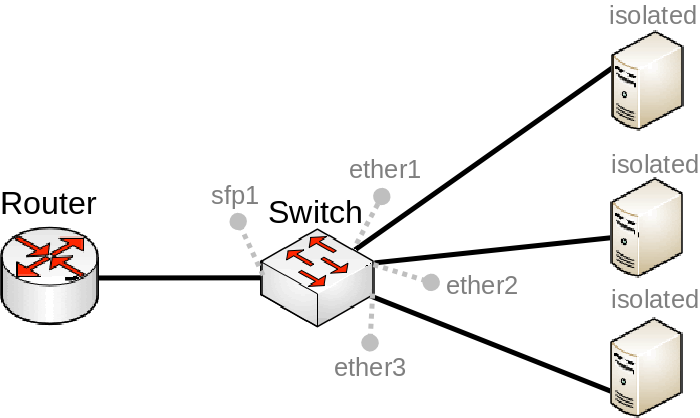
Private VLAN
In some scenarios you might need to forward all traffic to a uplink port while all other ports are isolated from each other. This kind of setup is called Private VLAN configuration, the Switch will forward all Ethernet frames directly to the uplink port allowing the Router to filter unwanted packets and limit access between devices that are behind switch ports.
To configure switch port isolation, you need to switch all required ports:
Override the egress port for each switch port that needs to be isolated (excluding the uplink port):
Note: It is possible to set multiple uplink ports for a single switch chip, this can be done by specifying multiple interfaces and separating them with a comma.
Isolated switch groups
In some scenarios you might need to isolate a group of devices from other groups, this can be done using the switch port isolation feature. This is useful when you have multiple networks but you want to use a single switch, with port isolation you can allow certain switch ports to be able to communicate through only a set of switch ports. In this example devices on ether1-4 will only be able to communicate with devices that are on ether1-4, while devices on ether5-8 will only be able to communicate with devices on ether5-8 (ether1-4 is not able to communicate with ether5-8)
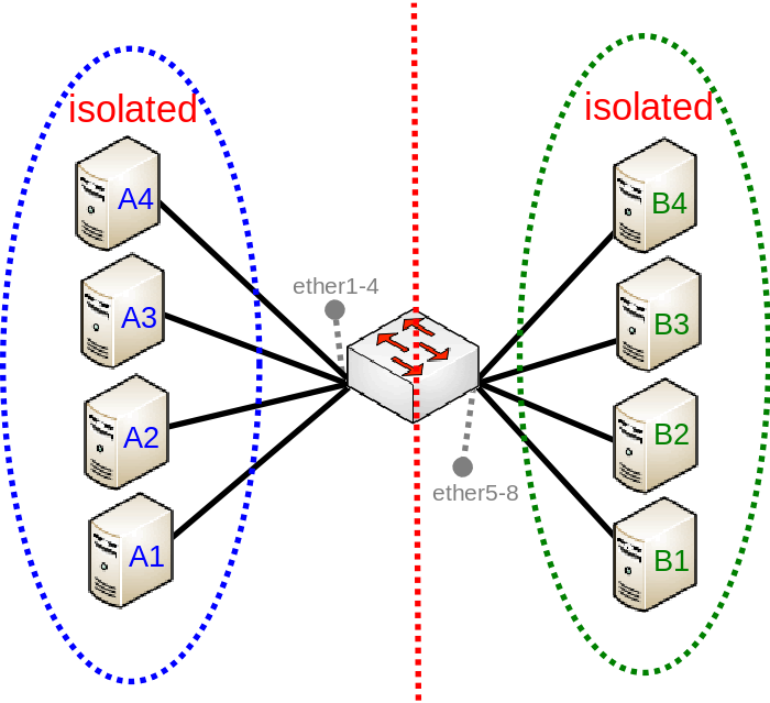
To configure isolated switch groups you must first switch all ports:
Then specify in the forwarding-override property all ports that you want to be in the same isolated switch group (except the port on which you are applying the property), for example, to create an isolated switch group for A devices:
To create an isolated switch group for B devices:
CPU Flow Control
All switch chips have a special port that is called switchX-cpu, this is the CPU port for a switch chip, it is meant to forward traffic from a switch chip to the CPU, such a port is required for management traffic and for routing features. By default the switch chip ensures that this special CPU port is not congested and sends out Pause Frames when link capacity is exceeded to make sure the port is not oversaturated, this feature is called CPU Flow Control. Without this feature packets that might be crucial for routing or management purposes might get dropped.
Since RouterOS v6.43 it is possible to disable the CPU Flow Control feature on some devices that are using one of the follow switch chips: Atheros8227, QCA8337, Atheros8327, Atheros7240 or Atheros8316. Other switch chips have this feature enabled by default and cannot be changed. To disable CPU Flow Control use the following command:
Statistics
Some switch chips are capable of reporting statistics, this can be useful to monitor how many packets are sent to the CPU from the built-in switch chip. These statistics can also be used to monitor CPU Flow Control. You can find an example of switch chip’s statistics below:
Some devices have multiple CPU cores that are directly connected to a built-in switch chip using separate data lanes. These devices can report which data lane was used to forward the packet from or to the CPU port from the switch chip. For such devices an extra line is added for each row, the first line represents data that was sent using the first data lane, the second line represent data that was sent using the second data line and so on. You can find an example of switch chip’s statistics for a device with multiple data lanes connecting the CPU and the built-in switch chip:
Setup Examples
Note: Make sure you have added all needed interfaces to the VLAN table when using secure vlan-mode. For routing functions to work properly on the same device through ports that use secure vlan-mode, you will need to allow access to the CPU from those ports, this can be done by adding the switchX-cpu interface itself to the VLAN table. Examples can be found at the Management port section.
Warning: When allowing access to the CPU, you are allowing access from a certain port to the actual router/switch, this is not always desirable. Make sure you implement proper firewall filter rules to secure your device when access to the CPU is allowed from a certain VLAN ID and port, use firewall filter rules to allow access to only certain services.
Note: It is possible to use the built-in switch chip and the CPU at the same time to create a Switch-Router setup, where a device acts as a switch and as a router at the same time. You can find a configuration example in the Switch-Router guide.
VLAN Example 1 (Trunk and Access Ports)
Switch together the required ports:
Add VLAN table entries to allow frames with specific VLAN IDs between ports:
Assign vlan-mode and vlan-header mode for each port and also default-vlan-id on ingress for each access port:
Note: For devices with QCA8337 and Atheros8327 switch chips a default vlan-header=leave-as-is should be used. When vlan-mode=secure is configured, it ignore switch port vlan-header options. VLAN table entries handle all the egress tagging/untagging and works as vlan-header=leave-as-is on all ports. It means what comes in tagged, goes out tagged as well, only default-vlan-id frames are untagged at the egress of port.
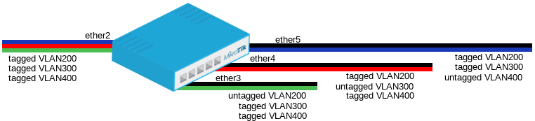
VLAN Example 2 (Trunk and Hybrid Ports)
VLAN Hybrid ports which can forward both tagged and untagged traffic are supported only by some Gigabit switch chips (QCA8337, Atheros8327)
Switch together the required ports:
Add VLAN table entries to allow frames with specific VLAN IDs between ports.
In switch port menu set vlan-mode on all ports and also default-vlan-id on planned hybrid ports:
Management access configuration
In these examples there will be shown examples for multiple scenarios, but each of these scenarios require you to have switched ports. Below you can find how to switch multiple ports:
In these examples it will be assumed that ether1 is the trunk port and ether2 is the access port, for configuration as the following:
Tagged
In order to make the device accessible only from a certain VLAN, you need to create a new VLAN interface on the bridge interface and assign an IP address to it:
Specify from which interfaces it is allowed to access the device:
Note: Only specify trunk ports in this VLAN table entry, it is not possible to allow access to the CPU with tagged traffic through an access port since the access port will tag all ingress traffic with the specified default-vlan-id value.
When VLAN table is configured, you can enable vlan-mode=secure to limit access to the CPU:
Untagged
Specify which access (untagged) ports are allowed to access the CPU:
Warning: Most commonly an access (untagged) port is accompanied with a trunk (tagged) port. In case of untagged access to the CPU, you are forced to specify both the access port and the trunk port, this gives access to the CPU from the trunk port as well. Not always this is desired and Firewall might be required on top of VLAN filtering.
When VLAN table is configured, you can enable vlan-mode=secure to limit access to the CPU:
Note: To setup management port using untagged traffic on a device with the Atheros7240 switch chip, you will need to set vlan-header=add-if-missing for the CPU port.
Untagged from tagged port
It is possible to allow access to the device from the trunk (tagged) port with untagged traffic. To do so, assign an IP address on the bridge interface:
Specify which ports are allowed to access the CPU. Use vlan-id that is used in default-vlan-id for switch-cpu and trunk ports, by default it is set to 0 or 1.
When VLAN table is configured, you can enable vlan-mode=secure to limit access to the CPU:
Note: This configuration example is not possible for devices with the Atheros8316 and Atheros7240 switch chips.